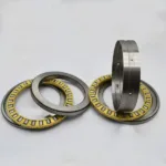
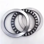
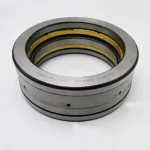
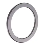
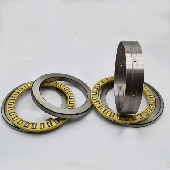
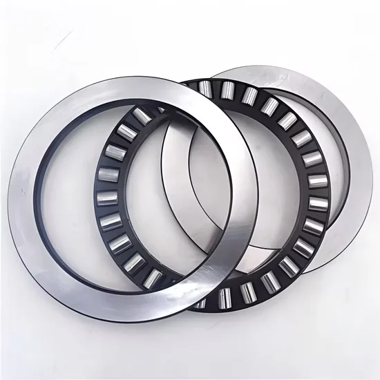
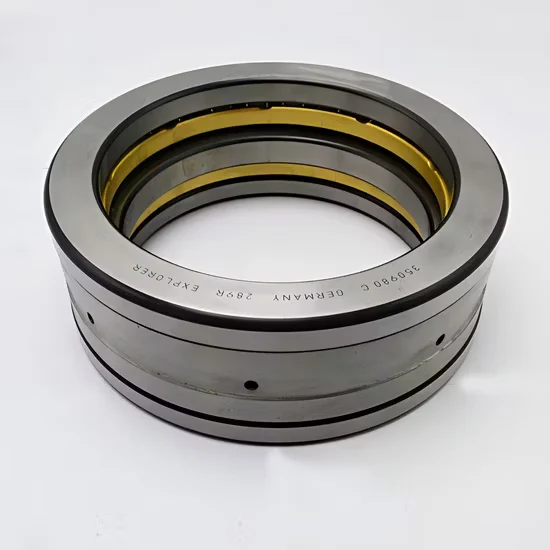
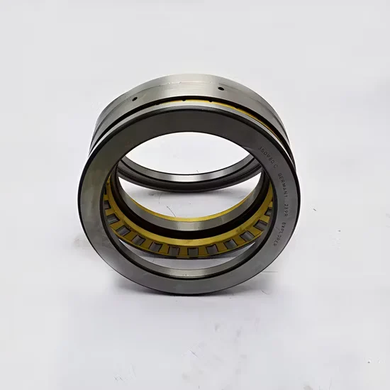
81106m 81107m 81108m 81109m Thrust Cylindrical Roller Bearing Heavy Load
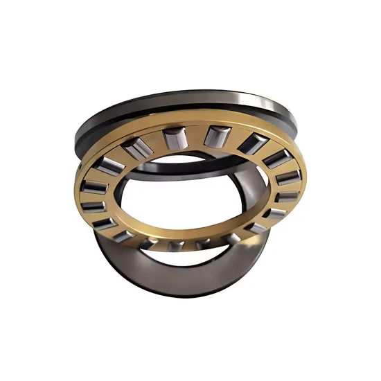
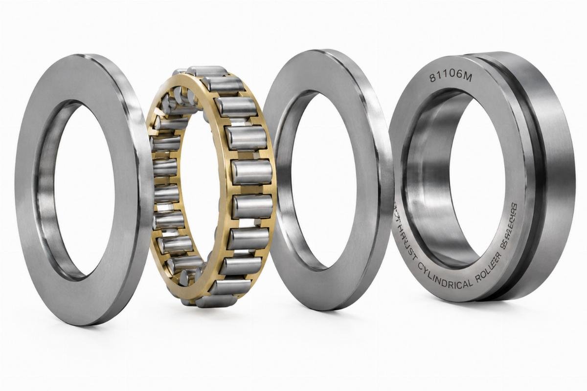
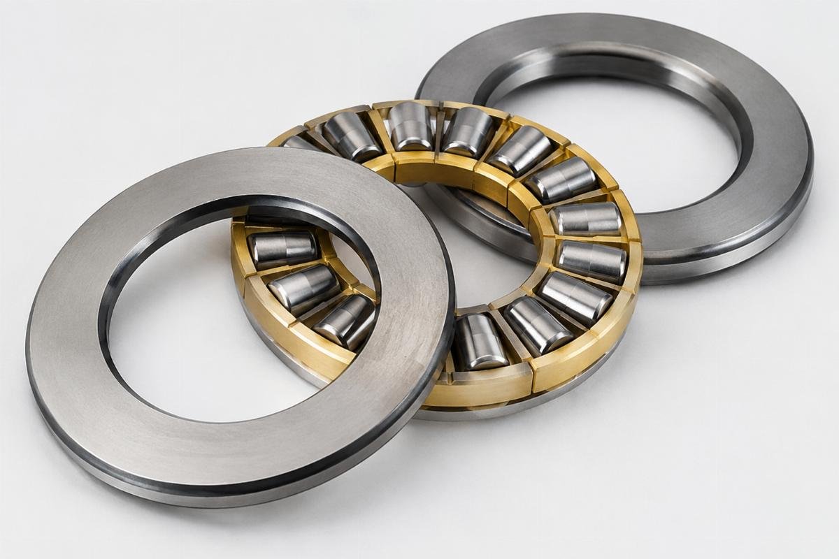
81106m Thrust Cylindrical Roller Bearing features separated components for simplified installation and Gcr15 chrome steel construction to handle pure axial loads in heavy duty, low speed machinery.
Single row non-aligning roller design optimized for lifting equipment and industrial gearboxes
Genuine traceability ensures strict cross-reference alignment of clearance, cage, and precision grades for your exact application requirements
Traceable Authenticity Verification — Every 81106m thrust cylindrical roller bearing ships with scannable QR codes linking directly to original mill test reports.
Technical Specifications
Parameter
Value
Designation
81106m
Product Type
Thrust Cylindrical Roller Bearing
Rolling Element
Roller
Number of Rows
Single
Material
Chrome Steel Gcr15 / 100cr6
Aligning
Non-Aligning
Load Direction
Thrust
Separated
Separated
Note: The suffix ‘m’ is an unverified suffix and requires manufacturer catalog confirmation for exact cage specifications.
Application Suitability
Industry
Typical Applications
Heavy Machinery
Crane slewing mechanisms and hoist drum axial supports
Machine Tools
Vertical boring mill worktable thrust supports
Lifting Equipment
Heavy-duty gearbox axial load carrying stages
Why Heavy-Duty Axial Supports Fail Before the Steel Yields
Material mismatch in the cage causes catastrophic breakdowns long before the rolling elements fatigue.
When sourcing an 81106m thrust cylindrical roller bearing for continuous low-speed, high-axial-load environments, engineers often focus exclusively on the basic dynamic load rating. Yet, field failure analysis reveals that a significant share of premature stops stems from cage material misalignment rather than raceway spalling [NEED_CITE: rolling bearing failure mode classification per ISO 15243]. In extreme conditions like steel mill continuous casters, specifying a stamped steel cage instead of a machined brass alternative under heavy shock loads leads to early structural fracture, bringing the entire production line to a halt.
Matching Component Geometry to Axial Force Profiles
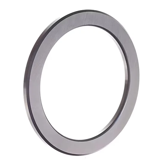
The separated design of this 81106m thrust cylindrical roller bearing allows maintenance crews to inspect the shaft washer, housing washer, and roller-cage assembly independently without dismantling the entire gearbox. This modularity is critical for lifting equipment where axial clearances must be precisely adjusted during reassembly. Our technical team cross-references dimensional drawings to ensure the exact bore and outside diameter match your housing tolerances, preventing micro-movements that accelerate wear.
Managing Low-Speed and High-Axial Stress Environments
Pure thrust loads at low rotational speeds prevent the formation of a full elastohydrodynamic lubrication film, increasing the risk of boundary lubrication and surface scuffing. The non-aligning geometry demands strict perpendicularity between the shaft and housing shoulders to avoid edge loading on the cylindrical rollers. Furthermore, heavy-duty gearboxes often operate in environments with high particulate contamination, requiring external sealing solutions since this separated configuration does not include integrated contact seals [NEED_CITE: lubrication film thickness calculations per ISO 281]. Proper grease selection with high extreme-pressure additives is essential to protect the Gcr15 raceways during startup.
Decoding the Separated Architecture and Material Selection
The single-row arrangement optimizes the contact area for pure axial load capacity, eliminating the radial load constraints typical of combined designs. Utilizing Chrome Steel Gcr15 / 100Cr6 provides the necessary core hardness and wear resistance for continuous heavy-load applications. Because the components are separated, the shaft and housing washers can be mounted with different interference fits depending on whether the load is rotating or stationary relative to the ring. The suffix ‘m’ in the designation requires manufacturer catalog confirmation to verify the exact cage material and dimensional tolerances, ensuring it aligns with your specific heavy-duty requirements.
The Operational Impact of Incorrect Cage Specification
Selecting an inadequate cage material for low-speed, high-thrust applications results in unplanned downtime and catastrophic damage to adjacent gearbox components. When the cage fractures under shock loading, the cylindrical rollers lose their spacing, skewing and jamming against the raceways. This secondary damage voids standard warranties and forces complete assembly replacements rather than simple bearing swaps. Adhering to failure analysis frameworks highlights that preventing cage fatigue is far more cost-effective than managing the collateral destruction of shafts and housings [NEED_CITE: secondary damage assessment in rolling bearings].
Securing Verified Supply Chains for Critical Axial Components
We maintain extensive spot inventory covering thousands of standard and special part numbers, ensuring urgent maintenance requirements for thrust bearings are met without extended lead times. Our engineering team provides cross-brand equivalent model consultation, verifying that alternative designs match the exact axial clearance and load capacity of your original specification. Every shipment includes complete traceability documentation, protecting your operations from counterfeit components that frequently infiltrate the heavy machinery MRO market. We also offer flexible consolidation shipments, allowing you to mix single-unit emergency spares with full container project orders to optimize sourcing costs.
Documentation & Authenticity
Certificate of Conformity validating the Gcr15 / 100Cr6 chemical composition for this specific batch.
Original mill test reports confirming the heat treatment hardness of the separated washers.
Dimensional inspection records verifying the perpendicularity tolerances of the thrust raceways.
Scannable authenticity tags linking the 81106m designation to the manufacturer’s production facilities.
Storage, Handling & Mounting
Store the separated washers and roller-cage assembly in original VCI packaging to prevent micro-corrosion on the Gcr15 raceways.
Keep the roller-cage set horizontal on a flat surface; suspending it vertically risks deforming the cage pockets.
Use induction heating for the shaft washer installation to achieve the required interference fit without damaging the cylindrical rollers.
Apply a high-viscosity EP grease to the thrust raceways immediately before mounting to prevent dry startup scuffing.
Engineering Data Required for Technical Validation
To ensure precise axial load matching, please share your equipment’s maximum thrust force, operating speed, and continuous duty cycle. Providing the OEM equipment number or existing housing dimensions allows our team to perform a thorough cross-reference check and L10 life calculation. If your application involves extreme shock loads or elevated temperatures, detail these environmental factors so we can recommend the optimal cage material and clearance class.
Frequently Asked Questions
Q: How do I differentiate between single-row and double-row thrust cylindrical roller bearings?
A: Single-row designs like this model handle pure axial loads in one direction and feature a simpler separated assembly. Double-row variants accommodate bidirectional thrust loads but require more complex housing geometries and precise axial preload adjustments. We can review your load vectors to determine which configuration prevents raceway unloading during directional shifts.
Q: What are the installation precautions for separated thrust bearings?
A: Since the shaft washer, housing washer, and roller-cage assembly are independent, they must be aligned perfectly during mounting to prevent edge loading. Ensure the shaft and housing shoulders are strictly perpendicular to the axis of rotation. Never apply mounting force through the cage or rolling elements, as this will permanently indent the Gcr15 raceways and cause early fatigue.
Q: How does Gcr15 chrome steel perform in heavy-load, low-speed conditions?
A: This material offers exceptional core hardness and wear resistance, making it ideal for resisting surface deformation under massive axial forces. However, at low speeds, the lubrication film is thinner, so the steel relies heavily on extreme-pressure additives in the grease to prevent scuffing. For highly corrosive environments, we can discuss alternative stainless steel options.
Q: What is the cross-reference equivalence for this designation across different brands?
A: While the basic dimensions remain standardized, internal geometries like cage design and roller profiles vary between manufacturers. We cross-reference to SKF, FAG, and NSK equivalents, verifying that the dynamic load rating and limiting speeds match your specific heavy-duty gearbox requirements. Always provide your exact operating parameters so we can validate the interchangeability.
Shipping Information
EU Warehouse
3-7 working days (bonded stock)
Direct from China
Shanghai & Ningbo hubs (bulk / FCL)
Markets Served
DE · IT · PL · ES · NL · FR · EU+
Incoterms
DDP / DAP available on request
Minimum Order
Contact us for MOQ details
Documents Included with Every Shipment
EN and ISO Quality Certificates
Batch traceability and manufacturing standard
Material & Heat-Treatment Reports
Full material composition and process records
CE Declaration of Conformity
For bearing units and motion products
RoHS Compliance Declaration
Restriction of hazardous substances
EUR.1 Movement Certificate
Preferential origin for EU customs
Certificate of Origin
Country of manufacture documentation
Correct HS Codes
Pre-classified for smooth customs clearance
Commercial Invoice & Packing List
VAT-compliant intra-EU invoicing
Transparent Landed Cost with Tax Explanation
SKFEU provides full price transparency so EU buyers know exactly what they pay. No hidden duties, no surprise charges at customs.
VAT-Compliant Invoicing
All intra-EU transactions are invoiced with correct VAT treatment. B2B buyers with valid EU VAT numbers receive zero-rated invoices where applicable.
No Unexpected Import Duties
Goods shipped from our EU bonded warehouse arrive as intra-EU movements -- no import duties, no customs delays for EU-based buyers.
EUR.1 & Origin Docs Ready
For shipments direct from China, EUR.1 movement certificates and certificates of origin are prepared in advance to minimise customs clearance time.
DDP Pricing Available
Ask for Delivered Duty Paid quotations -- we absorb all import costs so your landed cost is fixed and predictable from day one.
Need a landed cost breakdown? Contact Sofia at
sofia@skfeu.com
or via WhatsApp for a full DDP quotation including freight, duties and VAT for your country.
Send Inquiry
Request Pricing & Availability
Share your requirements and Sofia will respond within one working day with pricing, lead time and full documentation details.